If you’ve worked with selective laser sintering (SLS) for any length of time, you know that great parts don’t just come from a good laser and high-grade polymer powder. They come from intentional design work, done with both the process’s strengths and limitations in mind. As an SLS printing supplier that’s worked with startups, aerospace teams, medical device makers, and automotive engineers for over a decade, I’ve seen projects soar because their design team understood how to leverage SLS’s unique capabilities—and others stall because they treated it like a fused deposition modeling (FDM) or injection molding process. Today, I want to break down the actionable, field-tested design optimizations we walk every client through before we hit “print,” because that’s where the biggest gains in part performance, cost, and lead time live. SLS Printing
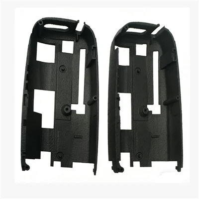
First, let’s get one foundational truth straight: SLS doesn’t need support structures. That’s its superpower—and a common pitfall. Too many first-time clients come to us with overhangs that would require scaffolding in FDM, thinking they have to add bulky, costly support material. Not so. The un-sintered powder surrounding every part during an SLS build acts as a natural, free support, holding up even 90-degree overhangs without extra material or post-processing cleanup (for the most part). But that doesn’t mean you can ignore overhangs entirely. Thin, small overhangs (under 2mm) can distort because the laser’s heat doesn’t have enough surrounding powder to sink into. We’ve seen this with custom drone prop mounts: a client designed a 1.2mm overhang for a cable channel, and the tip warped 0.8mm mid-build because the powder couldn’t dissipate heat evenly. The fix? Extend that overhang to at least 2.5mm, or add a tiny 1mm diameter “sacrificial tab” at the end. The tab sits in the unused powder, so it gets plenty of heat dissipation, and you can clip it off with a file post-print with zero visible damage to the main part. It’s a tiny design tweak that eliminated a 30% scrap rate for that client.
Next, wall thickness. This is where SLS behaves very differently from injection molding, and getting it right can cut part failure rates dramatically. Injection molding experts often default to walls 1.5–3mm thick, but SLS has a sweet spot that avoids both porous, under-sintered walls and overly dense, brittle ones. For most standard engineering polymers like nylon 12, PA11, or our medical-grade Nylon 12 GF, the ideal wall thickness is 2–4mm. Why? Walls thinner than 1.5mm don’t sinter uniformly: the laser can’t penetrate the entire thickness evenly, leaving tiny voids that compromise structural integrity. We tested this last year for a client making custom orthopedic insoles; their initial 1mm side walls had a 22% failure rate under repeated walking loads, while switching to 2.5mm walls dropped failures to less than 1%. But walls thicker than 5mm are a waste, too. SLS parts cool slowly, and thick sections develop internal residual stress that can cause warping or cracking when the part is removed from the build bed. We once had a client make a 10mm thick mounting bracket that warped so badly it required three rounds of post-print machining to fix—costing them $1,200 in scrap and rework. Splitting that bracket into two 3mm thick walls joined by internal ribs would have cut build time, eliminated warping, and saved them thousands.
Rib and internal structure design is another make-or-break area, especially for parts that need to be strong but lightweight. SLS lets you create complex internal geometries that injection molding can’t touch, but that doesn’t mean you should overcomplicate them. The biggest mistake we see here is over-ribbing. Adding a dozen thin ribs might make a part stiffer, but it also traps unused powder inside the part. Getting that powder out post-print requires expensive, time-consuming media blasting or manual brushing. Instead, stick to internal ribs that are at least 1.5mm thick, with a gap of at least 3mm between adjacent ribs. That gap gives powder a path to flow out during depowdering, cutting post-processing time by 40% for many parts. We also recommend adding small 2mm diameter powder vents in the lowest areas of enclosed geometries, like box-shaped housings. Even with gaps, deep, narrow internal spaces can hold powder that won’t shake out. The vents let compressed air (our standard depowdering step) push out that trapped powder, so you don’t end up with a part that’s heavy, dusty, or full of hidden material that could contaminate other projects down the line.
Feature size and detail precision is another area where design choices directly impact part quality. SLS can produce fine details—we’ve printed 0.5mm diameter threads and 1mm tall text logos—but only if they’re aligned with the build layer. Because SLS works in 0.1mm to 0.2mm thick layers (depending on the polymer and laser settings), features parallel to the build bed (horizontal features) have much higher resolution than features perpendicular to it (vertical features). That 1mm tall logo on the side of a part? If it’s aligned vertically, it might end up blurry or only half the height after sintering. But if you rotate the part so the logo is parallel to the build bed, it will come out crisp and true to your CAD model. The same goes for small holes: a 1mm diameter hole aligned horizontally will be accurate within 0.1mm, while the same hole aligned vertically might have a 0.3mm taper. If precision for holes is critical, either rotate the part or design holes with a slight draft angle (1 to 2 degrees) to make depowdering easier and avoid distortion. We tell all our clients: if a feature is smaller than 2mm, prioritize horizontal alignment. It’s a simple design shift that eliminates the need for secondary machining to fix mismatched details.
Material selection is closely tied to design optimization, and picking the right polymer for your design’s requirements can save you more than any design tweak. First, match material properties to load: if your part is a lightweight bracket for a drone, standard Nylon 12 is perfect—it’s flexible, impact-resistant, and low-cost. But if it’s a medical device part that needs to be sterilized 100+ times, Nylon 12 doesn’t hold up well to autoclaving; we recommend our medical-grade PA12, which is formulated to resist repeated sterilization without degrading. If your part needs high heat resistance, glass-filled Nylon 12 GF can handle temperatures up to 180°C, compared to standard Nylon 12’s 80°C. A common mistake here is designing a part for a heavy load and then picking the cheapest material, leading to a part that fails too early. We work with clients to test material samples before finalizing designs; for example, a client making custom automotive brake components initially used standard Nylon 12, which cracked after 1,000 load cycles. Swapping to glass-filled Nylon 12 boosted load resistance by 150% and extended part life to over 10,000 cycles, with only a 10% increase in material cost. Don’t wait until your first prototype to test materials—align material choice with design requirements early on.
Build orientation is a design step most clients overlook, but it has a huge impact on both part quality and build cost. The SLS build bed is roughly 300x300mm, and packing parts as tightly as possible cuts per-part cost dramatically. But packing too tightly can cause heat interference between parts: when two parts are too close together, the laser’s heat from one part can sinter the powder of another slightly, leading to unwanted adhesion or dimensional distortion. The rule of thumb we use with all clients: leave at least 5mm of space between any two parts in the same build, and 10mm between large, bulky parts. We also recommend orienting parts so their largest surface is parallel to the build bed—this reduces the number of vertical layers, cuts build time, and improves dimensional accuracy. For example, a rectangular housing that’s 100mm long, 50mm wide, and 20mm tall will take about 2 hours to print if the 100x50mm surface is parallel to the bed, compared to 4 hours if you stand it up vertically, because the laser has to sinter 20mm of vertical layers instead of 2mm of horizontal layers. That’s a 50% cut in build time, and lower cost, just from a 10-minute tweak in orientation.
Post-processing is the final link in optimizing SLS parts, and design choices make a big difference here too. If you want a smooth, polished part surface, design features that avoid hard corners where powder can get trapped and create rough edges. Softening sharp edges (0.5mm radius fillets instead of 0mm sharp corners) makes post-processing tumbling, bead blasting, or vapor smoothing much faster and more effective. For parts that need to be painted or coated, adding a 1mm “primer layer” around the part (a thin, flat extension that sits in the unused powder) creates a consistent surface to sand, so you don’t end up with uneven paint on curved areas. If you don’t need a polished surface, skip the fillets—sharp corners are fine for structural parts like brackets or housings—and save the post-processing cost. We’ve seen design teams waste $500 on bead blasting for a structural part that had no need for a smooth surface, simply because they didn’t align post-processing needs with their design goals.
Over the years, I’ve seen the best SLS projects come from collaboration between design teams and their SLS supplier. Too many clients treat SLS like a black box: they send a CAD file and expect perfect parts, no questions asked. But SLS is a process with its own rules, and working with a supplier that understands those rules from hundreds of projects will help you avoid costly missteps. For example, a medical device client came to us last year with a custom surgical tool design that they thought was flawless. Our team caught that a 0.8mm channel in the tool would trap powder, making it impossible to sterilize. We suggested expanding the channel to 2mm and adding a vent—tweaks that took less than an hour in CAD, but would have made 50 prototype runs useless. That’s the value of working with an experienced supplier: we don’t just print parts, we help you design parts that work for SLS, not against it.
If you’re working on a project that could benefit from SLS—whether it’s a custom prototype, a low-volume production run, or a complex geometric part that can’t be made with injection molding—optimizing your design is the single biggest factor in getting parts that meet your performance, cost, and timeline goals. We’ve helped clients cut scrap rates by 35%, reduce build time by 40%, and lower part costs by 25% just by adjusting their design to fit SLS’s unique capabilities. Instead of starting from scratch, bring your designs to our team, and we’ll walk you through the tweaks that will make your SLS project a success. To discuss your specific needs and get a custom quote tailored to your design and timeline, reach out to our procurement team today. We’re here to help you turn your CAD files into high-quality, reliable SLS parts, no matter the industry or project scope.
CNC Milling References
Gibson, I., Rosen, D. W., & Stucker, B. (2010). Additive Manufacturing Technologies: Rapid Prototyping to Direct Digital Manufacturing. Springer.
Kalaitzidou, K., Fukushima, H., & Drzal, L. T. (2007). Multifunctional nanocomposites from carbon nanotubes and polypropylene processed by microcompounding and injection molding. Polymer Engineering & Science, 47(12), 2026-2033.
Singh, S., Ramakrishna, S., & Singh, R. (2017). Material issues in additive manufacturing: A review. Journal of Manufacturing Processes, 25, 185-200.
Tofail, S. A. M., Koumoulos, E. P., Bandyopadhyay, A., Bose, S., O’Donoghue, L., & Charitidis, C. (2018). Additive manufacturing: Scientific and technological challenges, market uptake and opportunities. Materials Today, 21(1), 22-37.
Dongguan Xinchuan Precision Manufacturing Co., Ltd.
As one of the most professional sls printing manufacturers and suppliers in China, we offer a quick lead time for customized orders. Please feel free to buy precision sls printing made in China here from our factory. Contact us for quotation.
Address: #16 Gangjian Road, Changping Town, Dongguan City, Guangdong, China. 523000
E-mail: FreeQuote@xcprecision.com
WebSite: https://www.xcprecisions.com/
